Mission Purple Part 1: Powerflex Bushings Miata Polyurethane Bushings Installation

Rarely does a project pan out exactly as planned. That is the nature of car tuning projects. This is the case with our RallyWays Miata project of upgrading the suspension bushes with Powerflex polyurethane bushes. This is part 1 of the Miata polyurethane bushings installation. The disassembly.
Over on the blog, we published an article called Mission: Purple Polyurethane Bushings to Improve Car Handling. That article is the intro to this install. Be sure to read that first in order to fully understand what we’re trying to achieve here.
In this, Part 1, of the Poweflex bushes RallyWays Miata polyurethane bushings installation, I go into detail on the process and how it panned out, starting with disassembly. The goal is to improve the 1995 Miata suspension with the upgrade of Powerflex bushings. As the install went along, one thing led to another and next thing you know we’re 3 weeks in and the car’s still on jack stands.
The thing is, it’s quite the project to replace suspension bushings. Don’t get me wrong, it’s not hard. It’s just a little tedious and you need the right tools. You also need patience. And gloves. And patience. And another car… If you’re missing a specific tool and you’re in the middle of disassembly, you have to stop what you’re doing, clean up and head over to the hardware store to pick up what you need. As was the case with me on more than one occasion – Sometimes with something as simple as the depth of a metric socket. For example, I have a perfectly good 21mm socket. However it was too short for the removal of the upper front control arm pivot bolt. Adding an extension, even a short one would make it too long. Spaces around a Mazda Miata are sometimes kind of tight.
Starting the project – disassembly
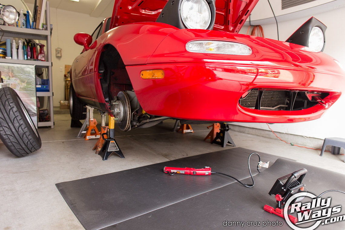
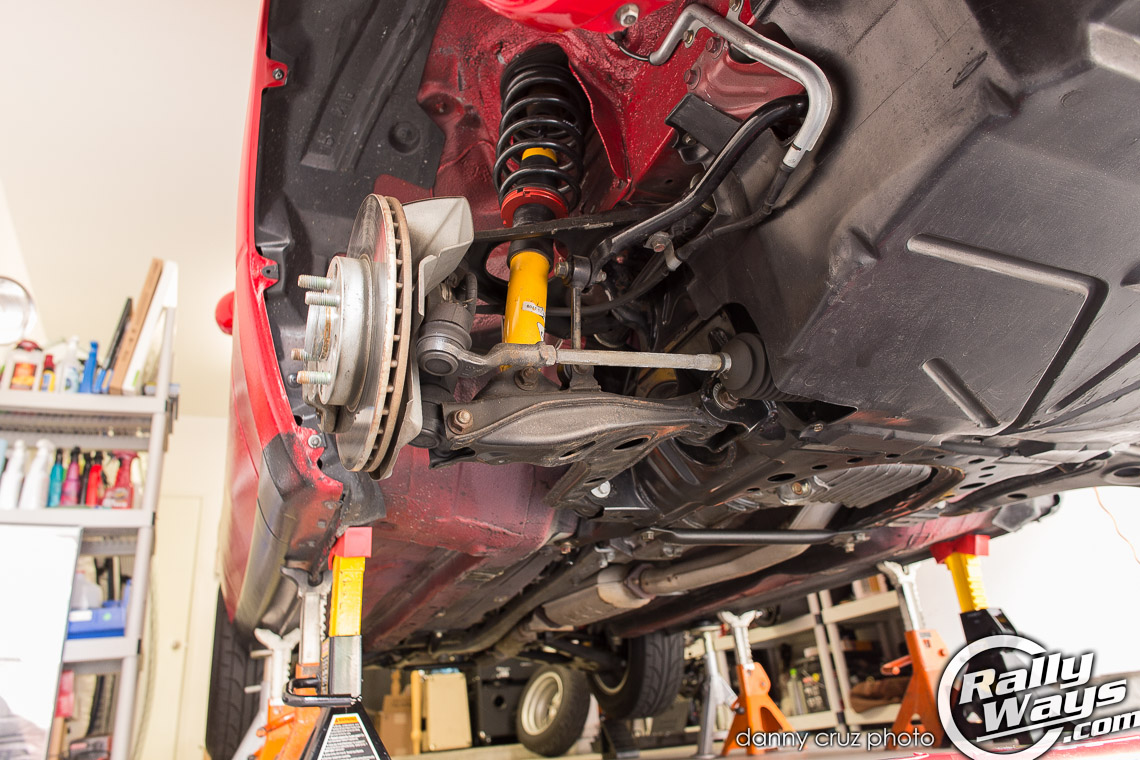
After getting the car up on jack stands I got together all the right metric sockets I needed based on the recommendations by Rod’s Miata service book. I decided to start with the front and complete that end first before moving on to the back. I figured it would be simpler as I didn’t have to deal with the drive wheel shafts at the back until later. Off came the wheels, then the brakes, the lower coilover pivot point and the lower ball joint unit. I couldn’t remove the steering tie rod from the pin end on the hub carrier as I didn’t have a ball joint remover handy so I just unscrewed it from the inner tied rod and counted the number of revolutions to 19 in order to keep the same toe-angle setting when reassembling. I wasn’t planning on removing the ball joints anyway, so no big deal.
I then marked the position of all the cam bolts on the lower wishbones using a white sharpie paint marker. The idea is to put them back at this exact position when rebuilding so that the suspension alignment wouldn’t be totally out of whack. I would be taking the car in for a professional alignment once finished, but I at least wanted to be close to the original setting. Then I proceeded to remove the cam bolts from the lower control arm and pull it out. This was on the driver’s side by the way.
Upon moving to the left upper wishbone I noticed that one was going to be a little trickier. Instead of individual bolts on each upper pivot point, like say, on a C6 Corvette, the Mazda NA Miata has one long bolt as a pivot point for the upper front control arm. This bolt needs to be wiggled out towards the front of the car. A task that proved to be rather a pain in the ass. This was when I had to do the first trip to the hardware store for a longer set of metric sockets. I also needed a breaker bar a bit shorter and less unwieldy than my 18″ Craftsman breaker bar. Home Depot had the the tool in the form of a 10″ 3/8″ drive Husky breaker bar. Vise grips clamped onto the shaft with a protective sheath in between, lots of penetrant spray and quite a while later, I got the darn thing out. So out came the upper wishbone along with the hub carrier dangling from it.
That’s when one thing led to another. As is the case with any mod or install, you need to make sure that the parts “around” your install are in good shape. Otherwise, you’re basically half-assing the job. After removing those parts I noticed a couple of things.
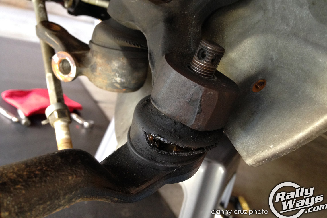
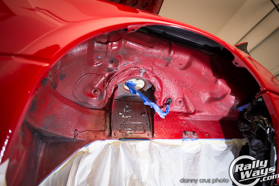
First, the rubber dust boots from all the ball joints – lower ball joint, upper ball joint and tie rod ball joints were are cracked and rotten. Those would need replacement. Maybe the ball joints themselves would need replacement. The control arms, while not rusty by any means, could use a bit of reconditioning. Cleaning them and power-coating them would be ideal. However, to keep the project within the budget I decided to clean them up nicely and rattle-can spray them with satin black. After testing the ball joints using the service manual’s method of testing, I decided the joints were in good condition, so it would only be a matter of replacing the rubber dust boots and repacking them with moly-grease. It also seemed to me the fender wells looked like crap so I cleaned them up with brake cleaner and took to the task of spraying them with black Rustoleum undercoating.
That’s a big benefit of doing the work yourself. If you were at a shop, the shop would’ve likely just installed the bushings as per your request, for the agreed upon estimate and maybe suggested new dust boots – probably new ball joints altogether. The fender wells and control arms would’ve been left as they are. At the shop there is no time to leave your car on the lift while you take the time to recondition things. You probably would’ve been stuck with whatever cheap aftermarket ball joints are available at Auto Zone, because the original Mazda dust boots are only available via special order. One big win for the DIYer.
However, that’s not to say the project doesn’t merit a professional shop install. This isn’t the easiest project to tackle. It’s easier than rebuilding an engine of course, but it’s more complicated than simply swapping out coilovers. You have to decide if the project is for you or for a mechanic to handle. If in doubt… mechanic. But then again. I’m not a mechanic. But somehow I’m not afraid of attempting anything. Well, I might not want to rebuild a transmission.
There was one more thing I wanted to do having gutted the front suspension. The front sway bar mounting points on stock NA and NB Miatas are known to be weak. With stock sways, these points are fine. But after upgrading to stiffer sway bars and stickier rubber, these points are known to crack. Since I would eventually be upgrading the front sway bar in my Miata, I knew I wanted to do something about this now, when there was more space to work.
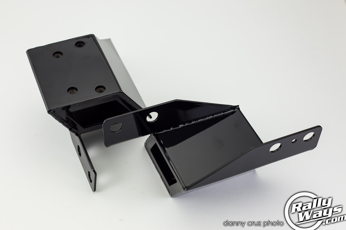
I decided to order a pair of AWR sway bar brackets to replace the stock brackets. The AWR sway bar mounts are beefy brackets used to replace the stock anti-roll bar mounting brackets and totally eliminate the problem of cracked mounting points. The downside is, they’re tricky to install. Next thing you know, I’m draining the cooling system to remove the radiator in order to make space for the AWR brackets installation.
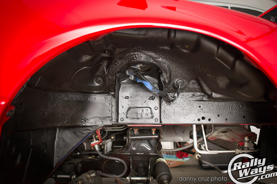
The stock anti-roll bar brackets in a Miata have 2 bolts on each side plus a spot weld on each side against the frame. Those have to be drilled out. In order to do so, the radiator needs to come out in order to make space for drilling and beating out the old brackets.
That last photo shows the space left by the stock Miata sway bar brackets removed.
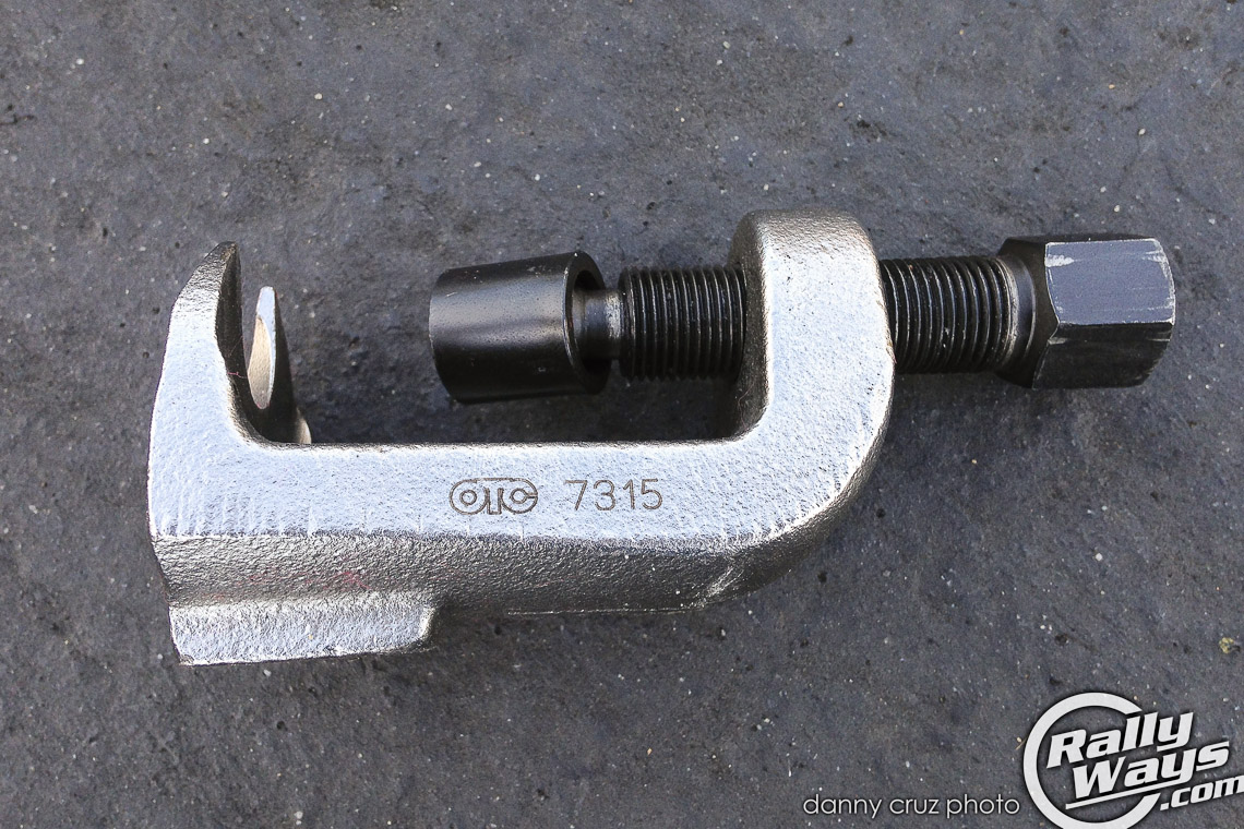
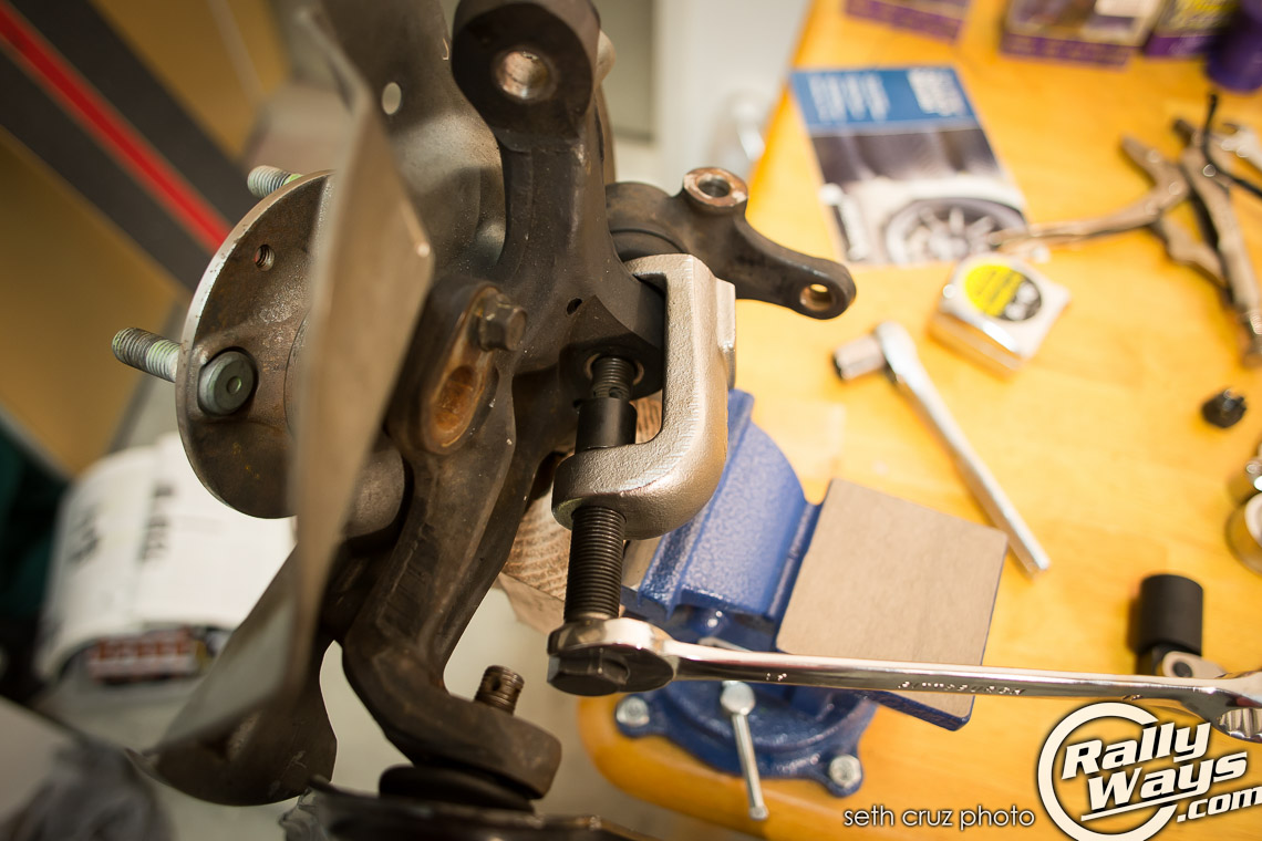
This is the tool I used to separate the ball joints from the hub carrier. This tool fit perfectly and much better than other ball joint separators I tried. With this one I was able to remove all three; the lower ball joint, upper ball joint and outer tie rods.
The tool is available for purchase here:
At some point during this process, I repeated the removal process for the passenger’s front side. By then, I had acquired the ball joint remover mentioned above that I borrowed from my good friend Mike, the owner of the 1991 Corvette ZR1 we featured last year. Needless to say, the right side was out in about an hour and a half. Much better progress.
What’s next
First, let’s see where we’re at.
1. Front wishbones top and bottom on each side are out.
2. Front coilovers are out and on the floor.
3. Ball joints top and bottom as well as outer tie rods were disconnected from the steering knuckle.
4. Fender wells were cleaned and painted with undercoating.
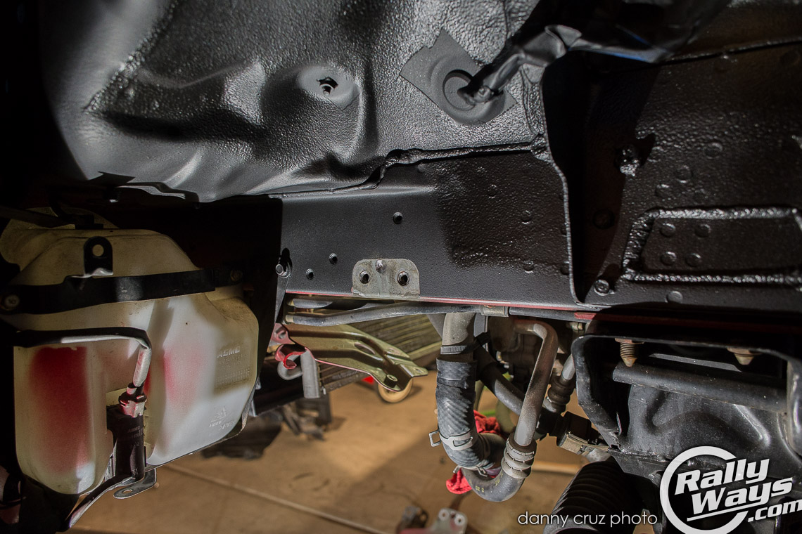
5. Radiator removed and AWR sway bar mounts nearly installed.
Now we turn to the control arms themselves. We need to take out the old bushings, clean and recondition the arms, paint them and install the new Powerflex bushes. I’m saying “we” because by now I find myself needing help, so my son jumps in to help.
Old bushing removal
There are many ways to remove the stock bushings. I like the environment. But Priuses suck. Regardless, I don’t believe in torching the old units out. Actual burning rubber is not good for anyone. I had heard of people successfully pushing out old bushes using a big c-clamp and a socket. However, I decided to run by Harbor Freight and and use one of their 25% off coupons instead. The trip to HB had me coming back home with a $30 (after discount) 1-ton arbor press which I then bolted to my workbench. The press is the number #3552 1 ton arbor press at Harbor Freight.
For convenience, Amazon also has the very same arbor press:
What I did to remove the old bushings without torching them:
1. The stock bushes have a lip on one side. I cut the lip of each of the bushings in order to push the bush through in the same direction it was original put in. The reason I did this was because I can only push on one side because of the way the control arm has to be placed on the press. That side happened to be the one with the lip on it. I had to remove it in order to push the bush through using that end.
2. Working on one bush at a time, I heated the target bush with an electric heat gun also from Harbor Freight. I heated the bush until the rubber started bubbling a bit.
3. After taking off the bottom circular plate off the arbor press I placed the control arm with the bushing over the slot in the base of the press. I then placed a 22mm socket over the bush at the top and with the arbor press piston (beam, plunger, pylon, whatever the heck that thing is called) I pressed down on the bush. Wearing safety goggles, I heaved and hoed on the lever until the bush came out the other end. The only way to do this is if the press is bolted securely to a strong-enough work bench. The bush needs to be VERY hot, close to the point of melting, but not burning. If it’s not hot enough, it isn’t going to come out.
4. The slot at the bottom of this press is large enough to fit the bush, but the bush basically gets lodged in the slot. I had a good pry bar ready to pry the bush out of the slot in the arbor press base before it cooled down.
5. Then I repeated that process on all of the bushes.
Below is a convenient photo visual of the entire process


The dirty work done
There you have it. That’s the dirty work done. Of course, I still have to repeat the process for the rear suspension, but now that I’ve done it for the front, the rear should flow more smoothly. There was a lot of experimenting on the front and the process described above took quite a bit of trial and error. See, even though I was following the service manual, tools available are always a little different therefore requiring different processes to complete. Rod’s service manual recommended I remove the old rubber bushes using a c-clamp. However, even the authors were a little concerned about the viability of the tool – they thought it might break. It also required me to source a piece of steel pipe of just the right size for a carrier where the old bush would be pushed into. I didn’t want to have to deal with that, so when I discovered that HB’s 1-ton press had a bottom slot just big enough to fit the bushings I decide to go that route. Glad I did.
On to part 2
So that’s part one of the Powerflex suspension bushings installation in the RallyWays Miata… And we haven’t installed a single bushing yet! No worries there. In part 2 we will look into the process of reconditioning the control arms and installing the new bushes. Stay tuned. I will link to it from this article once that part’s complete.


